
Most transparent LED film projects on glass facades do not fail because of the display. They fail because the glass, the mullions, the power route and the daylight were treated as afterthoughts. If you are planning to install transparent LED film on a curtain wall or a storefront glazing system, three questions decide the outcome long before anyone talks about pixel pitch: can the existing structure carry the assembly, where do power and signal physically run, and how much daylight and see-through visibility will be left when the job is done. This guide walks through those decisions in the order they are actually made on site, and ends with a checklist you can hand to an installer or a facade consultant.
It is also worth being clear about scope. General product installation guides cover how a film screen is unpacked, aligned and bonded to a pane. This article is about building integration — the point where a display becomes part of a glass facade and has to satisfy structural, electrical and daylight requirements at the same time. If you only need the basic product-level procedure, see our installation methods for LED film screens; everything below assumes that decision has already been made and the question is how to make it work on a real facade.
What “Glass Facade Integration” Actually Means
A transparent LED film is not a self-supporting screen. It is a thin, light-emitting layer that depends entirely on the glass and framing behind it. That single fact drives almost every engineering constraint on a facade project. On an interior window or a shopfront pane, the film can often be applied directly to the glazing with a relatively simple mounting approach. On a curtain wall, it has to coexist with mullions, transoms, spandrel zones, gaskets, drainage paths and movement joints that were designed without a display in mind.
The practical difference shows up in three areas:
- Substrate. A single pane in a controlled interior is a predictable surface. A facade may combine coated low-e glass, laminated units, insulated glazing and different pane sizes in the same elevation. Each has different optical behaviour and different tolerance for adhesives and heat.
- Structure. Anything attached to a curtain wall adds dead load and can change wind behaviour. The load path has to be understood rather than assumed.
- Services. A display needs power and data at every panel zone, plus somewhere to put controllers and power supplies. Facades rarely have spare capacity in the right place.
Our earlier overview of как прозрачные дисплеи применяются для стеклянных навесных стен covers the application scenarios. The sections below deal with the engineering decisions behind them.
Start With a Glass and Structure Survey

Before any layout is drawn, record what is actually installed. A survey that takes a day often prevents weeks of rework later. At minimum, capture:
- Glass build-up per zone: single, laminated or insulated; coating type and which surface it sits on; tint and any frit or ceramic pattern.
- Pane dimensions, joint widths and the position of mullions and transoms, including any irregular or trapezoidal units.
- Framing material, anchorage type and whether the system is stick-built or unitised.
- Available depth behind the glass, access to the cavity, and where maintenance can realistically reach.
- Orientation, shading from neighbouring buildings, and the hours of direct sun on each elevation.
- Existing electrical provision near the display zone, and the route to a distribution board.
Two items are consistently missed. The first is coated glass: a low-e or reflective coating can change both the perceived colour of the display and the amount of light reflected back into the room, so a mock-up on the actual glass type matters more than a spec sheet. The second is movement: facades expand, contract and drift under wind and thermal load, and a rigid display assembly that ignores those joints will eventually show stress at its edges.
If the building has a facade engineer or the original curtain wall drawings are available, use them. Where they are not, treat the survey as a measured record rather than an assumption, and have the mounting approach reviewed by someone qualified to sign off on it.
Load Limits and Mounting Options
Transparent LED film is light compared with conventional LED cabinets, which is exactly why it is chosen for glazing. “Light”, however, is not the same as “no load”. The film, its bonding layer or frame, any stiffeners, cabling and local power units all add mass to a system that was engineered for glass and wind, not for hung equipment.
The review should cover dead load on the pane and framing, the effect of added surface area on wind behaviour, and the way the assembly is restrained at its edges. Typical ranges vary by manufacturer and by facade system, so the only reliable inputs are the product’s specification sheet and the building’s own structural documentation. Do not size a mounting system from a generic number quoted in a brochure.
There are three common mounting strategies, each with a different consequence:
| Approach | Where it works | Main constraint to check |
|---|---|---|
| Direct bonding to the pane | Interior glazing, shopfronts, single panes with good access | Adhesive compatibility with coatings; removability; thermal expansion difference between film and glass |
| Frame or perimeter fixing into mullions | Unitised curtain walls, larger elevations, projects needing removal for service | Load transfer into framing; avoiding interference with gaskets and drainage; corrosion between dissimilar metals |
| Suspended or tensioned assembly | Large atriums, hanging installations, zones where the glass cannot take load | Independent support structure, fixing points above, and certification of the suspension |
Whichever route is chosen, write the load path down explicitly: film → adhesive or frame → mullion or independent support → primary structure. If that chain has a missing link, the design is not finished. The same discipline applies to thermal behaviour; our notes on engineered limits and thermal management for custom LED displays cover why heat accumulation in a glazed cavity deserves its own check.
Power and Signal Routing Without Blocking Light
This is where otherwise sound facade projects lose their transparency. The display itself may be see-through, but a poorly planned bundle of cables, power supplies and controllers across the middle of a window is not.
Plan services as a drawing exercise before anything is ordered. Work out where each panel zone gets power, how many drivers are needed, where they will physically sit, and how data reaches them. Then check the design against these constraints:
- Keep the viewing area clear. Run cables along mullions, transoms and spandrel zones rather than across the transparent field. Where a crossover is unavoidable, use the narrowest route and hide it within existing framing.
- Place power supplies where they can be serviced. A driver behind a sealed unitised panel is a driver that requires dismantling the facade to replace.
- Respect the cavity. Facades have drainage and ventilation paths. Blocking them to hide a cable tray can create condensation problems that are far more expensive than the display.
- Separate power and data where the manufacturer’s instructions call for it, and allow for the bend radius and connector access of the actual cable type.
- Plan for the control system early. Content source, playback hardware, network access and any building management integration all need a physical home and a power outlet.
A useful sanity check is to walk the elevation with the cable routes marked on the drawing and ask what a visitor will see from outside at eye level. Anything visible in that zone will read as a dark line across the glass, regardless of how transparent the film is.
Light Transmission, Daylight and Visual Comfort
Specification sheets usually quote a transparency figure, but the number that matters on a facade is how the finished assembly behaves in use. Three effects interact:
- Daylight into the building. Any added layer reduces transmitted light to some degree. On a deep floor plate or a north-facing elevation this may be negligible; on a shallow, sunlit office it can be the deciding factor.
- View out and view in. Transparency is directional. A film that looks almost invisible from inside at midday can appear as a reflective surface from outside at dusk, and vice versa.
- Display brightness versus ambient light. A west-facing facade in direct sun needs far more output than a shaded interior window. Brightness, contrast and the ability to dim on a schedule matter more here than the headline transparency percentage.
Reflections are the most common complaint after handover. Coated glass, adjacent polished surfaces and strong backlight can all produce glare that no amount of brightness tuning will fix. The only dependable test is a full-size mock-up on the actual glass, viewed at the times of day the space is used. Where the project is part of a wider building design, the discussion in transparent LED film screens in smart building architecture gives useful context on treating the display as a facade layer rather than a sign.
If the choice is still open between a film applied to glass and a glass-integrated display product, the differences between LED film screens and electro-optical glass screens are worth reviewing before the facade specification is frozen — retrofitting one for the other later is rarely practical.
Installation Sequence: A Practical Checklist
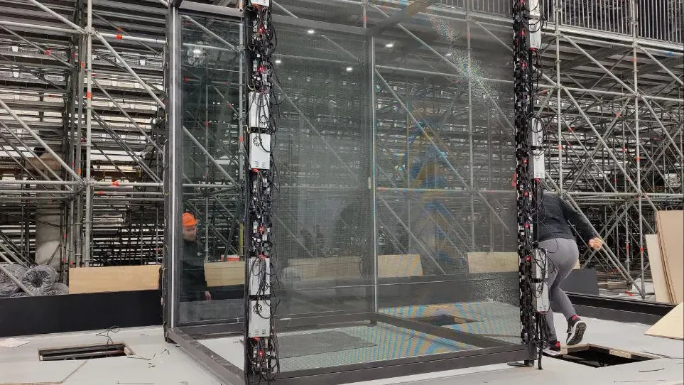
Exact procedures vary by product and manufacturer, so the following is a coordination sequence rather than a substitute for the installation manual. Use it to align the facade contractor, the display installer and the electrical contractor.
- Confirm the survey and mock-up. Verify glass type, dimensions, orientation and a full-size visual sample on the real substrate. Record colour and reflection behaviour at several times of day.
- Obtain structural sign-off. Agree the mounting method, load path and any independent support with the facade engineer before drilling or bonding anything.
- Freeze the services drawing. Mark panel zones, power supplies, controller location, cable routes, access points and isolation switches on one coordinated drawing.
- Check the substrate. Confirm coating compatibility, cleanliness, surface condition and the environmental limits for bonding (temperature and humidity on the day).
- Dry-fit and align. Position panels before fixing, check alignment against mullions and sightlines, and confirm panel-to-panel continuity across the elevation.
- Install in the manufacturer’s stated order. Follow the specified sequence for fixing, connection and any curing time; do not compress steps to meet a programme date.
- Route and conceal services. Keep cables within framing, protect drainage paths, label every run, and leave service loops where panels may need to be removed.
- Commission in real lighting. Calibrate brightness, colour and content at day and night conditions; set dimming schedules; test power-off behaviour and emergency isolation.
- Hand over documentation. As-built drawings, driver locations, replacement procedure, cleaning instructions and warranty conditions. Agree who owns facade access for future maintenance.
Common Mistakes on Glass Facade Projects
- Choosing the display before surveying the glass. Coatings and unitised panels can rule out an otherwise suitable product.
- Treating “lightweight” as “no structural review”. Added mass, wind behaviour and edge restraint still need a documented load path.
- Designing the cable route last. This is the single most common cause of visible wiring across the transparent field.
- Judging transparency from a brochure. Real appearance depends on glass build-up, orientation and time of day.
- Sealing in the power supplies. Equipment that cannot be reached without dismantling glazing will eventually dictate the maintenance budget.
- Ignoring movement joints and drainage. Both are there for a reason; a display assembly must accommodate them, not bridge them rigidly.
- Skipping the night-time test. A facade that performs well at noon can read very differently after dark, from both sides of the glass.
- Assuming one specification fits every elevation. A south-facing atrium and a shaded internal partition are different engineering problems.
Часто задаваемые вопросы
Заключение
A successful transparent LED film installation on a glass facade is mostly decided before the film arrives: an accurate glass survey, a documented load path, a coordinated services drawing and a mock-up judged in real daylight. Get those four right and the display itself becomes the straightforward part. Get them wrong and no amount of on-site adjustment will recover the transparency the project was sold on.
For project-specific questions about glass build-up, mounting or configuration, contact our team with your facade drawings and a description of the elevation; we can help identify which constraints need resolving first. If budget is the next question, our Справочник цен на прозрачные светодиодные экраны 2026 explains the commercial variables separately from the engineering ones covered here.


